SMT100 RS485 with Arduino
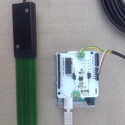
The SMT100 by TRUEBNER is one of the most accurate low cost soil moisture sensors on the market. I was really amazed by the accuracy and repeatability presented in a scientific publication from the Research Center Jülich in Germany and instantly ordered a sensor opting for the RS485 version. RS485 is the standard used in many industrial applications but only specifies the electrical signals. The message format or protocol is another story. The protocol used by the SMT100 RS485 is T-BUS. You will find a good description on wikipedia. Though the T-BUS protocol is a very well designed and flexible protocol it requires some efforts to implement on the Arduino. I was to lazy for that and found out that the SMT100 is also capable of unterstanding simple ASCII commands. So I decided to spent a few minutes to write a small Arduino test program. Of course you do need a piece of hardware to interface an RS485 sensor to the Arduino. I had an RS485 shield from Sparkfun lying around but any of the other RS485 shields on the market should do the job as well and you only habe to spent a few bucks. The SMT100 has 4 wires which have to be connected to the shield as follows:
- brown (Vcc, +5V)
- white (GND)
- green (RS485A)
- yellow (RS485B)
This is how the setup looks like:
This is the code I have been using:
#include <SoftwareSerial.h>
SoftwareSerial mySerial(2,3);
String str;
void setup() {
mySerial.begin (9600);
Serial.begin(9600);
}
void loop() {
if(Serial.available() > 0)
{
str = Serial.readStringUntil('\n');
mySerial.println (str);
delay(1000);
if (mySerial.available() > 0){
str = mySerial.readStringUntil('\n');
Serial.println(str);
} else {
Serial.println("no response from sensor");
}
}
}
There are two serial ports, the serial port to the PC and the software serial port to the RS485 shield. It is important to choose the right pins for TX and RX. RS485 in this case is half duplex, so you have to switch between TX and RX. On my shield this is automatically done when sending out data on the TX line. On other shields you may have to set a certain pin to transmit and release fo receive. On my shield this manual switching is also possible by appropriate jumper settings but I again took the lazy way relying on the automatic switching. The Arduino code waits for commands from the PC serial port. After hitting return on the keybord the command is transmitted to the sensor via the RS485 shield. Response time may be a few 100 ms and to be sure I introduced a one second delay before checking availability of data which is printed to the serial port to the PC again. Thats all.
Here are some examples of available commands:
Command: GetTemperature!
Answer: Temperature in degrees celsius
Command: GetWaterContent!
Answer: Volumetric water content in %
RS485 is a bus system so can you have more than one sensor attached. In this case it is important to configure each sensor with an individual address. During addressing only one sensor shall be on the bus. In order to set the address of a sensor to 1 you should enter:
Command: SetAddress!1
Answer: 1
You can check the address with:
Command: GetAddress!
Answer: 1
The commands to interrogate a sensor with address 1 are:
Command: GetTemperature!1
Answer: Temperature in degrees celsius
Command: GetWaterContent!1
Answer: Volumetric water content in %