SMT100 with LoRaWAN (TheThingsNetwork) and Dragino

After I have already carried out the first tests with LoRa and soil moisture sensors some time ago, a larger project is on the agenda for this year's gardening season.

Over the winter, I have been intensively occupied with LoRaWAN and also canvassed the relevant providers. At Dragino I found a very cheap LoRa module, which has a RS-485 interface. The advantage is that you can easily connect a SMT100 soil moisture sensor with Modbus (RS-485). The LoRa module also takes care of the power supply of the SMT100. The Litihium battery is even already supplied by Dragino. It's almost a plug-and-play system except for some minor software configuration work. What do you need to get started:

  1. Dragino RS-485BL LoRaWAN RS-485/UART converter
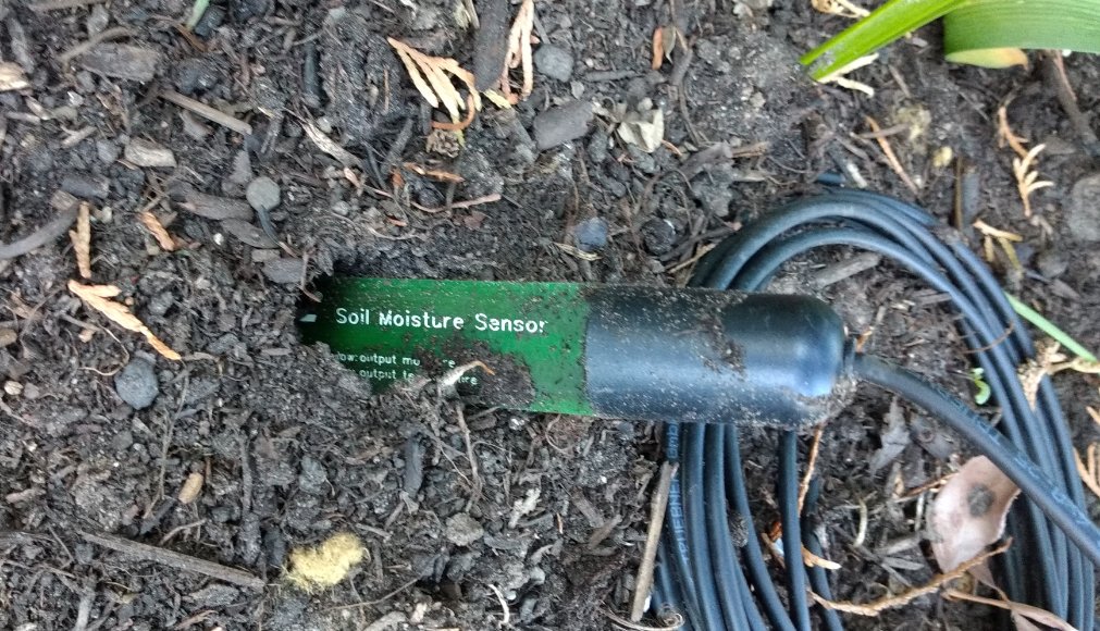
  2. SMT100 RS-485 soil moisture sensor from TRUEBNER (Modbus version)
  3. USB to TTL cable (3.3V) for software configuration

and of course a LoRaWAN gateway nearby. For me it is a TheThingsNetwork gateway, but other LoRaWAN systems should also work. The LoRa module must be registered with the LoRaWAN operator. For TheThingsNetwork, Dragino provides instructions in the LoRa module manual. TheThingsnetwork gateway near me still uses version 2 of TheThingsnetwork. In the course of the year 2021 it should be changed to version 3. Then the settings will change a bit. But now we stay with version 2 for the time being.

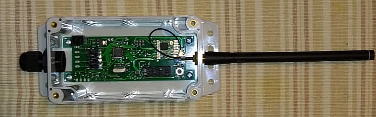
In the box of the LoRa module there is a sticker with all possible keys, EUIs, addresses and the serial number.

  • DEV ADDR
  • DEV EUI
  • APP EUI
  • APP KEY
  • APPSKEY
  • NETSKEY

After logging into TheThingsNetwork Console a new application is created. The APP EUI from the sticker is added via addEUI. Then a new device is created. It is very important to enter the DEV EUI, the APP EUI and the APP KEY from the sticker. Voilá, that's it for now with TheThingsNetwork and we go to the LoRa module. (Note: With other keys and EUIs you can certainly also work, but then have greater configuration effort on the module side).

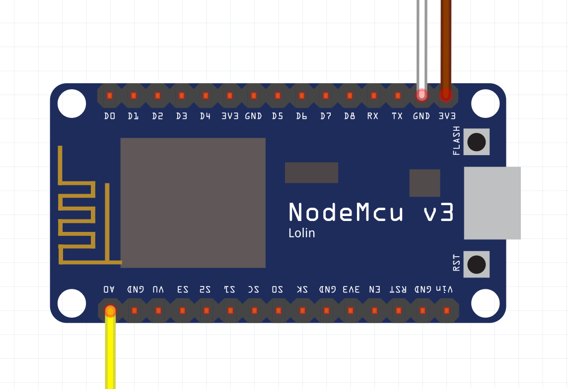
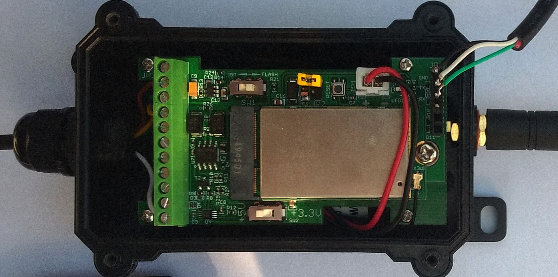
The next step is to connect the SMT100 RS-485 soil moisture sensor with the LoRa module as follows (left green socket for screwing, attention: look up exact assignment in the Dragino manual!):

  • Brown wire +5 V
  • White wire GND
  • Green wire RS-485 A
  • Yellow wire RS-485 B

Then connect the USB to TTL cable for configuration (right socket for pin headers, attention: look up exact assignment in Dragino manual!):

  • GND
  • UART_TXD
  • UART_RXD

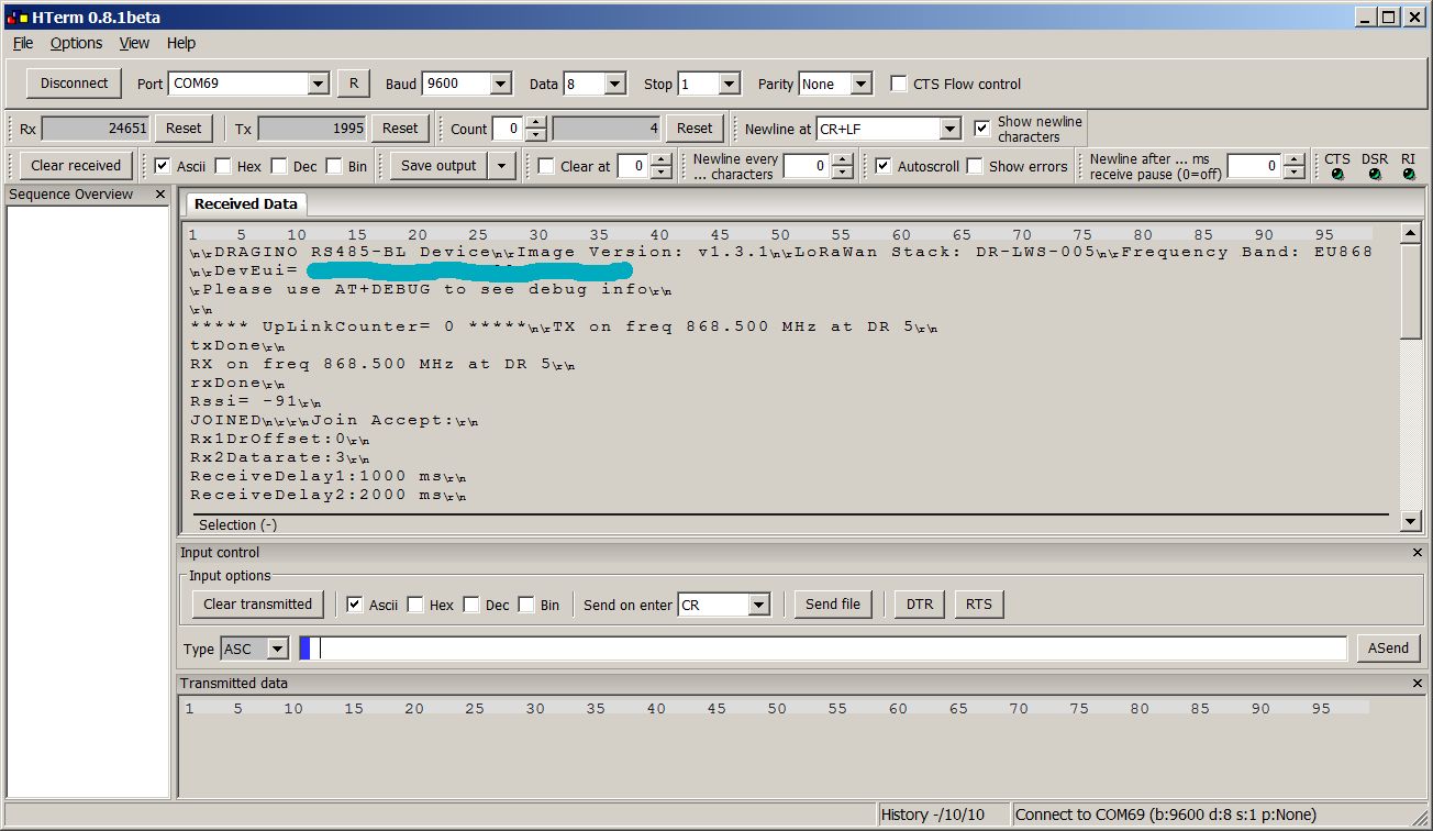
Please make sure that the USB TTL cable has 3.3 V level (TX from LoRa module to RX from cable, RX from LoRa module to TX from cable, if necessary check exactly how the cables are assigned and the connections are defined). I used a cheap cable from Ebay (about 4 Euro) and made sure that a FT232 USB chip is used. This usually does not give driver problems. I prefer to use HTerm as terminal program. The switches on the LoRa module must be set to 5V and Flash. The jumper for the supply of the module with the battery voltage must of course also be plugged. in HTerm you see the start of the module after plugging the power supply jumper.

Now you can configure the SMT100 by entering the password in HTerm (123456) and then send AT commands (Attention: Always capitalize commands and don't forget the CR at Send on Enter).

  • AT+BAUDR=9600 (9600 baud)
  • AT+PARITY=2 (even parity)
  • AT+5VT=100 (wait 100ms after turning on the 5 V supply for the sensor)
  • AT+MBFUN=1 (enable Modbus)
  • AT+COMMAND1=fd 03 00 00 00 01,1 (Temperature)
  • AT+COMMAND2=fd 03 00 01 00 01,1 (Soil moisture)
  • AT+DATACUT1=0,0,0
  • AT+DATACUT2=0,0,0
  • AT+TDC=60000 (Transmission interval, 60 s = 60000 ms)

You may check settings with:

  • AT+BAUDR=?
  • AT+PARITY=?
  • AT+5VT=?
  • AT+MBFUN=?
  • AT+COMMAND1=?
  • AT+COMMAND2=?
  • AT+DATACUT1=?
  • AT+DATACUT2=?
  • AT+TDC=?

The communication between the LoRa module and the connected SMT100 can be tested using AT+CFGDEV. Here is an example:

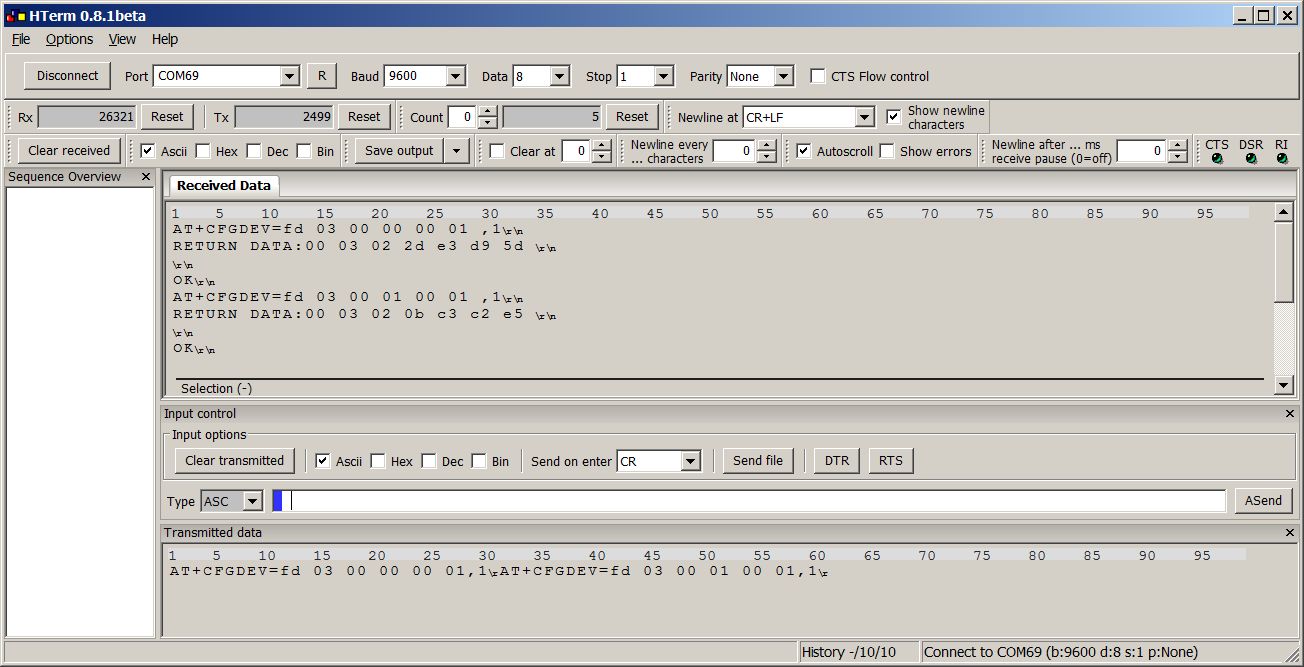
For explanation you should have the application note for Modbus from TRUEBNER ready.

The byte sequence fd 03 00 00 00 01 sends a Modbus broadcast to the one connected sensor and expects the temperature. The temperature is stored in the response in the 4th and 5th byte as a 16 bit number. If 2d e3 is converted to a decimal value, 11747 is obtained. If 11747 is divided by 100 and 100 is subtracted, 17.47°C is obtained. The byte sequence fd 03 00 01 00 01 sends a Modbus broadcast to the one connected sensor and expects the soil moisture. The soil moisture is stored in the response in the 4th and 5th byte as a 16 bit number. If 0b c3 is converted to a decimal value, 3011 is obtained. If 3011 is divided by 100, 30.11% is obtained as volumetric water content.

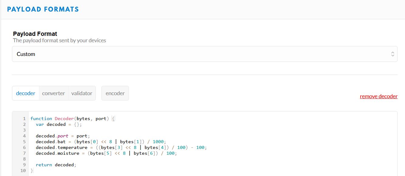
After the successful test the USB cable can be removed and the LoRa module is ready for operation. Now you can go back to TheThingsboard and watch the LoRa communication, but before that you should set a TTN decoder, so that the transmitted byte sequences are interpreted correctly. The decoder used here looks like this and extracts battery voltage, temperature and soil moisture from the data. (Note: The LoRa module transmits the battery voltage and also a payload version value by default, but we do not consider it here).

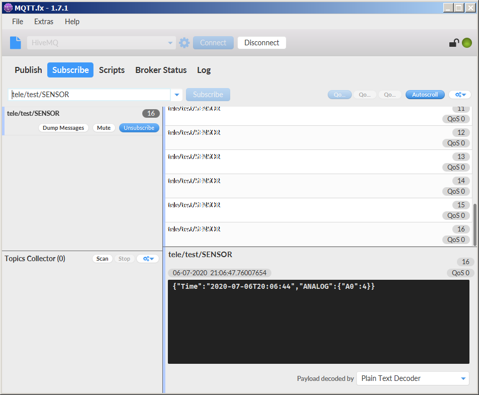
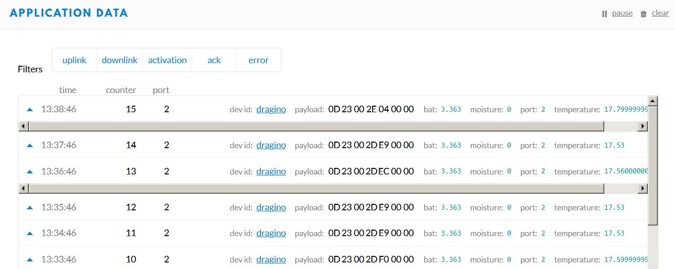
The following screenshot shows the data packets with the individual bytes and the decoding.

What is the next step? There is still a visualization missing, for which there are several possibilities. I use MQTT to fetch the measured values from TheThingsNetwork and then import the data into my Thingsboard system. I will describe that soon. For now I enjoy the spring sun with coffee and a delicious piece of crumble cake.


SMT100 mit LoRaWAN (TheThingsNetwork) und Dragino

Nachdem ich vor einiger Zeit schon einmal mit LoRa und Bodenfeuchtesensoren die ersten Versuche durchgeführt habe, steht für die diesjährige Gartensaison ein größeres Projekt an.

Über den Winter habe ich mich intensiv mit LoRaWAN beschäftigt und auch die einschlägigen Anbieter abgeklappert. Bei Dragino bin ich fündig geworden und zwar mit einem sehr günstigen LoRa-Modul, das eine RS-485 Schnittstelle hat. Der Vorteil ist, dass man ganz einfach einen SMT100 Bodenfeuchtesensor mit Modbus (RS-485) anschließen kann. Das LoRa-Modul übernimmt dabei auch die Stromversorgung des SMT100. Die Litihium Batterie wird von Dragino sogar schon mitgeliefert. Es ist bis auf ein paar kleine Softwarekonfigurationsarbeiten fast schon ein Plug-and-Play System. Was braucht man für den Start:

  1. Dragino RS-485BL LoRaWAN RS-485/UART converter
  2. SMT100 RS-485 Bodenfeuchtesensor von TRUEBNER (Modbus Version)
  3. USB nach TTL Kabel (3.3V) zum Konfigurieren der Software

und natürlich ein LoRaWAN Gateway in der Nähe. Bei mir ist es ein TheThingsNetwork Gateway, andere LoRaWAN Systeme sollten aber auch funktionieren. Das LoRa-Modul muss beim LoRaWAN Betreiber angemeldet werden. Für das TheThingsNetwork stellt Dragino im Handbuch zum LoRa-Modul die entsprechenden Anweisungen bereit. Das TheThingsnetwork Gateway bei mir in der Nähe nutzt noch die Version 2 von TheThingsnetwork. Im Laufe des Jahres 2021 soll auf Version 3 umgestellt werden. Dann werden sich die Einstellungen etwas ändern. Jetzt bleiben wir aber erst einmal bei Version 2.

Im Karton des LoRa-Moduls befindet sich ein Aufkleber mit allen möglichen Keys, EUIs, Adressen und der Seriennummer.

  • DEV ADDR
  • DEV EUI
  • APP EUI
  • APP KEY
  • APPSKEY
  • NETSKEY

Nach dem Einloggen in die TheThingsNetwork Console wird eine neue Application angelegt. Die APP EUI vom Aufkleber fügt man über addEUI hinzu. Dann wird ein neues Device erstellt, Ganz wichtig ist jetzt, dass man die DEV EUI, die APP EUI und den APP KEY vom Aufkleber einträgt. Voilá, das war es erst einmal mit TheThingsNetwork und wir gehen zum LoRa-Modul. (Hinweis: Mit anderen Keys und EUIs kann man sicher auch arbeiten, hat dann aber größeren Konfigurationsaufwand auf der Modulseite).

Im nächsten Schritt verbindet man den SMT100 RS-485 Bodenfeuchtesensir mit dem LoRa-Modul wie folgt (linke grüne Leiste zum Schrauben, Achtung: genaue Belegung im Dragino Handbuch nachschauen!):

  • Brauner Draht an +5 V
  • Weißer Draht an GND
  • Grüner Draht an RS-485 A
  • Gelber Draht an RS-485 B

Dann schließt man zum Konfigurieren das USB nach TTL Kabel an (rechte Buchse für Stiftleisten, Achtung: genaue Belegung im Dragino Handbuch nachschauen!):

  • GND
  • UART_TXD
  • UART_RXD

Bitte darauf achten, dass das USB TTL Kabel 3.3 V Pegel hat (TX vom LoRa-Modul auf RX vom Kabel, RX vom LoRa-Modul auf TX vom Kabel, ggf. genau nachschauen, wie die Kabel belegt und die Anschlüsse definiert sind). Ich habe ein günstiges Kabel von Ebay verwendet (ca. 4 Euro) und darauf geachtet, dass ein FT232 USB Chip verwendet wird. Das gibt in der Regel keine Treiberprobleme. Ich verwende als Terminalprogramm am liebsten HTerm. Die Schalter auf dem LoRa-Modul müssen auf 5V und Flash stehen. Der Jumper für die Versorgung des Moduls mit der Batteriespannung muss natürlich auch gesteckt sein. in HTerm sieht man nach dem Stecken des Stromversorgungsjumpers das Starten des Moduls.

Jetzt geht es an die Konfiguration des SMT100.Dazu gibt man in HTerm das Passwort ein (123456) und kann danach AT Kommandos absetzen (Achtung: Kommandos immer groß schreiben und nicht das CR bei Send on Enter vergessen!).

  • AT+BAUDR=9600 (9600 baud)
  • AT+PARITY=2 (gerade Parität)
  • AT+5VT=100 (100ms warten nach dem Einschalten der 5 V Versorgung für den Sensor)
  • AT+MBFUN=1 (Modbus einschalten)
  • AT+COMMAND1=fd 03 00 00 00 01,1 (Temperatur abfragen)
  • AT+COMMAND2=fd 03 00 01 00 01,1 (Bodenfeuchte abfragen)
  • AT+DATACUT1=0,0,0
  • AT+DATACUT2=0,0,0
  • AT+TDC=60000 (Sendeintervall einstellen, 60 s = 60000 ms)

Überprüfen geht durch:

  • AT+BAUDR=?
  • AT+PARITY=?
  • AT+5VT=?
  • AT+MBFUN=?
  • AT+COMMAND1=?
  • AT+COMMAND2=?
  • AT+DATACUT1=?
  • AT+DATACUT2=?
  • AT+TDC=?

Die Kommunikation zwischen dem LoRa-Modul und dem angeschlossenen SMT100 kann mit Hilfe von AT+CFGDEV getestet werden. Hier ist ein Beispiel:

Zur Erläuterung sollte man die Application Note zu Modbus von TRUEBNER bereithalten.

Die Bytetolge fd 03 00 00 00 01 sendet einen Modbus Broadcast an den einen angeschlossen Sensor und erwartet die Temperatur. Die Temperatur ist in der Antwort im 4. und 5. Byte gespeichert als 16 bit Zahl gespeichert. Wandelt man 2d e3 in einen Dezimalwert um, so erhält man 11747. Teilt man 11747 durch 100 und zieht noch 100 ab, so erhält man 17,47°C. Die Bytefolge fd 03 00 01 00 01 sendet einen Modbus Broadcast an den einen angeschlossen Sensor und erwartet die Bodenfeuchte. Die Bodenfeuchte ist in der Antwort im 4. und 5. Byte gespeichert als 16 bit Zahl gespeichert. Wandelt man 0b c3 in einen Dezimalwert um, so erhält man 3011. Teilt man 3011 durch 100, so erhält man 30,11% als volumetrischen Wassergehalt.

Nach dem erfolgreichen Test kann das USB Kabel wieder entfernt werden und das LoRa-Modul ist betriebsbereit. Jetzt kann man wieder zurück zu TheThingsboard und kann die LoRa Kommunikation beobachten.Vorher sollte man jedoch einen TTN Decoder einstellen, damit die übertragenen Bytefolgen auch richtig interpretiert werden. Der hier verwendete Decoder sieht so aus und extrahiert Batteriespanung, Temperatur und Bodenfeuchte (moisture) aus den Daten. (Hinweis: Das LoRa Modul überträgt standardmäßig die Batteriespannung und auch einen Payload Versionswert, den wir aber hier nicht betrachten).

Der nachfolgende Screenshot zeigt die Datenpakete mit den einzelnen Bytes und der Decodierung an.

Was kommt als nächster Schritt? Es fehlt ja noch eine Visualiserung.Dafür gibt es verschiedene Möglichkeiten. Ich nutze MQTT zum Abholen der Messwerte bei TheThingsNetwork und spiele die Daten dann in mein Thingsboard System ein. Das werde ich demnächst beschreiben. Jetzt genieße ich erst einmal die Frühlingssonne mit Kaffee und einem leckeren Stück Streuselkuchen.


SMT50 mit ESP8266 und Tasmota

Der ESP8266 ist ein sehr preisgünstiger Mikrocontroller mit eingebautem Wifi, der sich für drahtlose Sensoranwendungen perfekt eignet. Zur Bewässerungssteuerung soll der Bodenfeuchtensor SMT50 von TRUEBNER angeschlossen werden. Der SMT50 liefert zwei analoge Ausgangssignale. Da der ESP8266 nur einen analogen Eingang besitzt, wird nur der Bodenfeuchtewert oder der Temperaturwert übertragen. Mit einem zusätzlichen externen AD-Wandler können auch beide Werte gesendet werden. In diesem Projekt soll jedoch die einfachste Lösung erprobt werden.

Benötigt werden:

Verbinden Sie das NodeMCU-Board mit dem Computer und starten Sie das Flashtool als Administrator. Wählen Sie anschließend den COM-Port und die Firmware aus. Stellen Sie zuletzt „Erase flash“ auf „yes, wipes all“ und drücken Sie „Flash NodeMCU“.

Trennen Sie nach dem Flashen das Micro-USB-Kabel und verbinden Sie es erneut. Es sollte ein WLAN-Access-Point mit dem Namen tasmota-xxxx auftauchen, mit dem Sie sich verbinden müssen. Nun öffnet sich automatisch der Browser, indem WLAN-Einstellungen konfiguriert und gespeichert werden können. Stellen Sie SSID und Passwort Ihres WLANs ein. Dann "SAVE" drücken und das NodeMCU startet neu und sollte sich mit Ihrem WLAN automatisch verbinden.

Über das Control-Panel Ihres Routers können Sie die IP-Adresse des NodeMCU herausfinden, welche Sie in der Browser-Suchleiste eingeben müssen. Es wird eine Weboberfläche zum Konfigurieren angezeigt, durch die man analoge- bzw. digitale Ein- und Ausgänge, sowie die MQTT-Verbindung einstellen kann. Unter „Configure“ --> „Configure Modul“ muss nun der Modultyp ausgewählt und „A0 ADC0“ auf „Analog (1)“ gestellt werden.

Geben Sie anschließend unter „Configuration“ --> „Configure MQTT“ den MQTT-Host, den Port, die ClientID, sowie den Benutzernamen und das Passwort an und speichern Sie es. Das fertige Topic lautet tele/“Ihr Topic“/SENSOR. In idesem Beispiel wurde zum Test der Public Broker von HiveMQ verwendet.

Stecken Sie danach das Mikro-USB-Kabel aus dem NodeMCU und verbinden Sie den SMT50 wie folgt:
Braun an Pin „3V3“
Weiß an Pin „GND“
Gelb für den volumetrischen Wassergehalt, oder Grün für die Temperatur an den Pin „A0“.

Stecken Sie das Mikro-USB-Kabel wieder in den NodeMCU.

Wahlweise können Sie eine MQTT-Dashboard-App aus dem AppStore oder PlayStore installieren und identisch zur Ihrer MQTT-Konfiguration einstellen.

Auf dem PC können Sie mit Hilfe von MQTT.fx auch die Daten anschauen. Die Konfiguration sieht so aus:

Danach kann man das Topic subscriben und die Daten sehen.

Voilà, es funktionniert!

Wireless soil moisture sensor with LoRa

My nephew visited me some months ago and asked me for a wireless soil moisture sensor. At that time I was already aware of those groundbreaking new wireless technologies like LoRa, Sigfox and NB-IoT, but had no comprehensive experience so far. So I decided to

  • get an overview of the competing technologies LoRa, Sigfox and NB-IoT,
  • develop some low cost wireless nodes
  • and get some practical experience.

This is the first part of my journey which covers LoRa. Before diving into the technical details let me talk about low power long range communication in general.The range of a wireless system mainly depends on these factors

  • transmitter power
  • receiver sensitivity (bandwidth)
  • antenna gain
  • radio environment (from line of sight to dense urban areas)

Many people are not aware that the radio environment has an extreme infkuence in range. There is easily a factor of 10 or morge in range comparing rural and urband sites. Datasheets often claim a range which can only be achieved under most favourite conditions and therefore disappointment is guaranteed.  I usually follow these rules:

  • use the highest transmitter power which is accpetable in regard to frequency spectrum regulations and power supply capability
  • use antennas with as much gain as possible
  • place the antennas as high as possible
  • use a low bandwidth/datarate to increase sensitivity (in my application I usually transmit only a few bytes of data)

Before LoRa it was already possible to achieve long range at low power, but LoRa made this possible at very low cost by integrating the required signal processing into a single chip. I usually go with the module RFM95 by HopeRF which is about 5-6 Euros and add an ATmega328 controller. Here you can see me first attempt.

Software is either pure LoRa or LoRaWAN in conjunction the TheThingsNetwork. For LoRaWAN I chose MCCI Catena LMIC lib which works quite well and a low power lib to achieve a few Mikroamps during sleep times. This way I am running an experiemental node in my garden together with an SMT50.