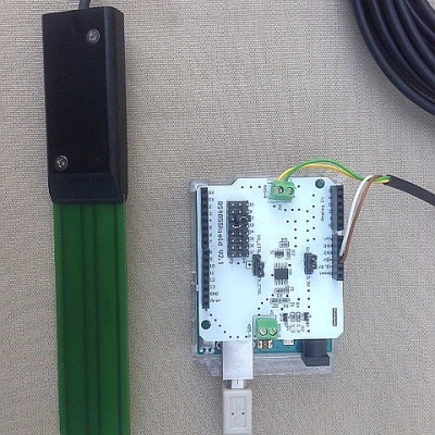
SMT100 with 4 - 20 mA interface

The 4 - 20 mA interface or current loop is still very popular in process control automation. There are a couple of advantages:

  • Only 2 wires are required (if sensor is low power and requires less than 4 mA current)
  • Voltage drop along the interconnection wires does not degrade accuracy, so extremely long cables are possible
  • Broken cable can be identified (no current)
  • High noise immunity (because of relatively high currents)

The disadvantage is:

  • Power consumption high and relatively high supply voltages required (typically 12 V to 24 V DC)

Generally I prefer digital interfaces like RS-485, but easy to use  4 - 20 mA sensor are ideally suited for my farmsite so that even untrained personnel can install or replace sensors without configuration hassle.

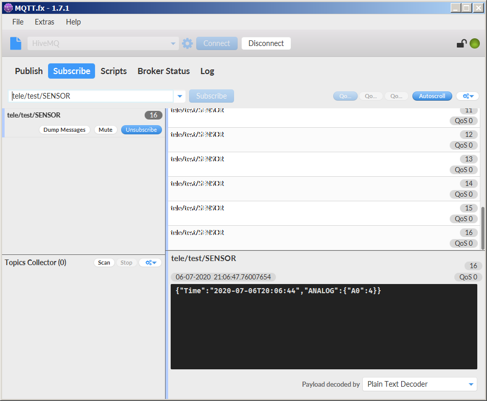
The choice of 4 - 20 mA sensors for soil moisture measurement is quite limited. Besides other disadvantages, Chinese sensors like Sonbus SM2801 or those from Rika are not real 2 wire sensors. A converter module by Vegetronix for voltage output sensors does not help as well since it requires an external power supply, so no real 2 wire solution as well. Even higher quality sensors like Gropoint are not a 2 wire solution. In the end I only found one real 2 wire solution which is from Decagon (now Metergroup) with their MAS-1 (and probably some OEM variants which look exactly the same). Unfortunately the manual of the MAS-1 contained an unpleasant surprise. The accuracy in volumetric water content is 6% which is mediocre but acceptable. What is more worrying is that the sensor air shall transmit approximately between 3.4 mA and 4.7 mA. I believe this is quite a very large tolerance since I hoped that at least in air it should be quite close to 4 mA. Fortunately a 4 - 20 mA variant of the SMT100 recently came on the market. I already own a couple of SMT100 with RS-485 interface for my garden irrigation system which are working fine, so I decided to give it a try with a SMT100 4 - 20 mA, which arrived these days. My first test was current measurement in air and the SMT100 was 4.03 mA, so right on spot. Even with 100 m cable length no degradation could be observed. So this is a good start for my upcoming farmsite project I hopefully can report on in the future.

SMT50 mit ESP8266 und Tasmota

Der ESP8266 ist ein sehr preisgünstiger Mikrocontroller mit eingebautem Wifi, der sich für drahtlose Sensoranwendungen perfekt eignet. Zur Bewässerungssteuerung soll der Bodenfeuchtensor SMT50 von TRUEBNER angeschlossen werden. Der SMT50 liefert zwei analoge Ausgangssignale. Da der ESP8266 nur einen analogen Eingang besitzt, wird nur der Bodenfeuchtewert oder der Temperaturwert übertragen. Mit einem zusätzlichen externen AD-Wandler können auch beide Werte gesendet werden. In diesem Projekt soll jedoch die einfachste Lösung erprobt werden.

Benötigt werden:

Verbinden Sie das NodeMCU-Board mit dem Computer und starten Sie das Flashtool als Administrator. Wählen Sie anschließend den COM-Port und die Firmware aus. Stellen Sie zuletzt „Erase flash“ auf „yes, wipes all“ und drücken Sie „Flash NodeMCU“.

Trennen Sie nach dem Flashen das Micro-USB-Kabel und verbinden Sie es erneut. Es sollte ein WLAN-Access-Point mit dem Namen tasmota-xxxx auftauchen, mit dem Sie sich verbinden müssen. Nun öffnet sich automatisch der Browser, indem WLAN-Einstellungen konfiguriert und gespeichert werden können. Stellen Sie SSID und Passwort Ihres WLANs ein. Dann "SAVE" drücken und das NodeMCU startet neu und sollte sich mit Ihrem WLAN automatisch verbinden.

Über das Control-Panel Ihres Routers können Sie die IP-Adresse des NodeMCU herausfinden, welche Sie in der Browser-Suchleiste eingeben müssen. Es wird eine Weboberfläche zum Konfigurieren angezeigt, durch die man analoge- bzw. digitale Ein- und Ausgänge, sowie die MQTT-Verbindung einstellen kann. Unter „Configure“ --> „Configure Modul“ muss nun der Modultyp ausgewählt und „A0 ADC0“ auf „Analog (1)“ gestellt werden.

Geben Sie anschließend unter „Configuration“ --> „Configure MQTT“ den MQTT-Host, den Port, die ClientID, sowie den Benutzernamen und das Passwort an und speichern Sie es. Das fertige Topic lautet tele/“Ihr Topic“/SENSOR. In idesem Beispiel wurde zum Test der Public Broker von HiveMQ verwendet.

Stecken Sie danach das Mikro-USB-Kabel aus dem NodeMCU und verbinden Sie den SMT50 wie folgt:
Braun an Pin „3V3“
Weiß an Pin „GND“
Gelb für den volumetrischen Wassergehalt, oder Grün für die Temperatur an den Pin „A0“.

Stecken Sie das Mikro-USB-Kabel wieder in den NodeMCU.

Wahlweise können Sie eine MQTT-Dashboard-App aus dem AppStore oder PlayStore installieren und identisch zur Ihrer MQTT-Konfiguration einstellen.

Auf dem PC können Sie mit Hilfe von MQTT.fx auch die Daten anschauen. Die Konfiguration sieht so aus:

Danach kann man das Topic subscriben und die Daten sehen.

Voilà, es funktionniert!

SMT100 RS485 with Arduino

The SMT100 by TRUEBNER is one of the most accurate low cost soil moisture sensors on the market. I was really amazed by the accuracy and repeatability presented in a scientific publication from the Research Center Jülich in Germany and instantly ordered a sensor opting for the RS485 version. RS485 is the standard used in many industrial applications but only specifies the electrical signals. The message format or protocol is another story. The protocol used by the SMT100 RS485 is T-BUS. You will find a good description on wikipedia. Though the T-BUS protocol is a very well designed and flexible protocol it requires some efforts to implement on the Arduino. I was to lazy for that and found out that the SMT100 is also capable of unterstanding simple ASCII commands. So I decided to spent a few minutes to write a small Arduino test program. Of course you do need a piece of hardware to interface an RS485 sensor to the Arduino. I had an RS485 shield from Sparkfun lying around but any of the other RS485 shields on the market should do the job as well and you only habe to spent a few bucks. The SMT100 has 4 wires which have to be connected to the shield as follows:

  • brown (Vcc, +5V)
  • white (GND)
  • green (RS485A)
  • yellow (RS485B)

This is how the setup looks like:

This is the code I have been using:

#include <SoftwareSerial.h>

SoftwareSerial mySerial(2,3);

String str;

void setup() {

  mySerial.begin (9600);

  Serial.begin(9600);

}

void loop() {

    if(Serial.available() > 0)

    {

        str = Serial.readStringUntil('\n');

        mySerial.println (str);

        delay(1000);

        if (mySerial.available() > 0){

          str = mySerial.readStringUntil('\n');

          Serial.println(str);

          } else {

             Serial.println("no response from sensor");

          }         

    }

}

There are two serial ports, the serial port to the PC and the software serial port to the RS485 shield. It is important to choose the right pins for TX and RX. RS485 in this case is half duplex, so you have to switch between TX and RX. On my shield this is automatically done when sending out data on the TX line. On other shields you may have to set a certain pin to transmit and release fo receive. On my shield this manual switching is also possible by appropriate jumper settings but I again took the lazy way relying on the automatic switching. The Arduino code waits for commands from the PC serial port. After hitting return on the keybord the command is transmitted to the sensor via the RS485 shield. Response time may be a few 100 ms and to be sure I introduced a one second delay before checking availability of data which is printed to the serial port to the PC again. Thats all.

Here are some examples of available commands:

Command: GetTemperature!

Answer: Temperature in degrees celsius

Command: GetWaterContent!

Answer: Volumetric water content in %

RS485 is a bus system so can you have more than one sensor attached. In this case it is important to configure each sensor with an individual address. During addressing only one sensor shall be on the bus. In order to set the address of a sensor to 1 you should enter:

Command: SetAddress!1

Answer: 1

You can check the address with:

Command: GetAddress!

Answer: 1

The commands to interrogate a sensor with address 1 are:

Command: GetTemperature!1

Answer: Temperature in degrees celsius

Command: GetWaterContent!1

Answer: Volumetric water content in %


How to install soil moisture sensors

Installation of a capacitive soil moisture probe is simple. However, there are a few important points which should be considered in order to achieve a good measurement result.

So here is some field work in my garden.

The figure below shows the correct installation of the SMT50 soil moisture sensor. It is mandatory to fully burry the probe including the black housing. A very good contact to the surrounding soil with no air gaps is very important because air gaps will lead to wrong soil moisture measurements. The density of the surrounding soil will influence the measurement signal. Make sure, the soil is properly compressed.


For irrigation purpose the SMT50 should be installed close to the roots of the plants. The ideal orientation of the sensor is a horizontal position. It is important to turn the sensor in an uprigth position so that no water can be accumulated on the surface of the green measurement area.

Sometimes it can be useful to embed two or more sensors in different depths. Then it is possible to see the penetration of the waterfront during the irrigation process. Based on this data the irrigation can be optimized.

Do not use a hammer for installation of the SMT50. If the soil is very compressed, it is recommended to use a punch or to soften up the soil by adding water.
 

The cable of the SMT50 is very robust and can directly be burried inside any type of soil. However, sometimes it can make sense to protect the cable against animal bites by using an additional ductwork.
 

Typical installation errors are shown below.

Temperature sensor is not burried in the soil -> Wrong temperature measurement

Measurement electrodes not fully burried -> Wrong moisture measurement

Large distance between sensor and dripping lines -> Sensor reacts to late / no reaction

Sensor is positioned to close to the wall of a pot -> Wrong moisture measurement

Sensor is inside granular material with air gaps -> Wrong moisture measurement

Cable connections inside the (wet) soil -> Wrong output signal of the sensor


Soil moisture sensor SMT50 and Arduino

The SMT50 by TRUEBNER is perfectly suited for the Arduino. The wiring is shown in the picture above.

  • brown: 3.3 V - 30 V
  • white: ground
  • green: temperature (voltage output with 10 kOhm output resistance)
  • yellow: moisture (voltage output with 10 kOhm output resistance)

Arduino code is also pretty simple, just read the analog voltages as shown in the code snippet below:

const int measurements = 50;

float temperatureArray[measurements];
float sensorValueTemperature = 0.0;
float moistureArray[measurements];
float sensorValueMoisture = 0.0;

for (int i = 0; i < measurements; i++)
{
    temperatureArray[i] = analogRead(A0);
    moistureArray[i] = analogRead(A1);
}
 
for (int i = 0; i < measurements; i++)
{
    sensorValueTemperature += temperatureArray[i];
    sensorValueMoisture += moistureArray[i];
}


sensorValueTemperature = sensorValueTemperature / measurements;
sensorValueMoisture = sensorValueMoisture / measurements;

sensorValueTemperature = sensorValueTemperature*3.3/1024;
sensorValueMoisture = sensorValueMoisture *3.3/1024;
 
sensorValueTemperature = (sensorValueTemperature-0.5)*100;
sensorValueMoisture = sensorValueMoisture *50/3;
 
sensorValueTemperature = sensorValueTemperature*10;
sensorValueMoisture = sensorValueMoisture*10;

Please note that I measured 50 times the same analog channel and calculated the mean value to reduce any noise which may appear. The Arduino analog digital converter uses 3.3 V reference voltage. With 10 bit resolution you have 1024 steps. I first calculated the voltage, e.g. from

sensorValueTemperature = sensorValueTemperature*3.3/1024;

and then convert voltage into moisture according to the datasheet ( 0 V = 0% moisture, 3 V = 50 % moisture)

sensorValueMoisture = sensorValueMoisture *50/3;


Soil moisture sensor comparison

How to control irrigation? This is what I have been asked so many times. For me the answer is pretty simple. I do not trust weather forecast based irrigation control since rain amount can be extremely different from one to the other location especially in summer times with thunderstorms and other localized rain events. Therefore I recommend a couple of soil moisture sensors placed on site. But what kind and brand of soil moisture sensor to choose? There are so many sensors out there that is hard to decide which is the best one for your application. For price sensitive applications I now go with the TRUEBNER SMT50 after mixed experience with the Vegetronix VH400. I recently found a comparison between the SMT50 and the VH400 which shed light on the detailed technical differences between these sensors, see here.