Voltage divider in sensor applications
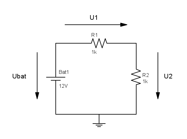
The voltage divider is extensively covered in many references like Wikipedia. In the example above the battery voltage of 12 V is applied to the series connection of two equal resistors. Therefore both voltages U1 and U2 are equal and half of the battery voltage. This basic concept often causes confusion when applied to sensors with voltage output. E.g. in my irrigation system I am using the professional but low cost soil moisture and temperature sensor SMT50. It has voltage outputs both for soil moisture and temperature. According to the datasheet the output resistance is 10 kOhms. So the sensor is equal to a voltage source with 10 kOhms resistance in series. If you connect the sensor to a multimeter which has a very high input impedance in the order of many Mega- or Gigaohms then the voltage drop at the 10 kOhms resistor is negligible. You will measure the voltage of the sensor which is in the range of 0 to 3 V depending on soil moisture and temperature (see characteristic curves in the datasheet). The situation may completely change if you connect the sensor to an irrigation controller with lower impedance. E.g. some of my farm buddies use the Loxone home automation controller. According to the Loxone documentation the analog input resistance is 10 kOhms. This means that the sensor voltage is divided by a factor of two. 3 V sensor output will be recognized as 1.5 V with the Loxone controller. This is no problem at all since you can simply multiply in Loxone software by a factor of two.